Product Features

Easily and finely adjust the system startup time with the shift function
Shift function
Using this function, the set shifting amount to conversion value can be added (shifted) to the digital output value.
When the shifting amount to conversion value is changed, it is reflected to the scaling value (digital operation value) in real time. Therefore, fine adjustment can be easily performed when the system starts.
For L60AD4
■ Before adjustment
| Input voltage (V) | Digital output value |
|---|---|
| 0 | -10 |
| 5 | 19990 |
■ After adjustment
| Input voltage (V) | Scaling value (digital operation value) |
|---|---|
| 0 | 0 |
| 5 | 20000 |
Reduce the time taken for programming
Scaling function
The scaling function converts values directly to easy-to-understand units without requiring any programming.
Since a separate conversion program is not required, the number of overall programming steps can be reduced.
Scaling settings example (L60AD4)
Normally an analog input of 4 to 20 mA is converted to a digital value from 0 to 20000. Using the scaling feature, the same input can result in a digital value of ±20000.
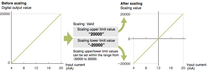
| Input current (mA) | Digital output value | Scaling value |
|---|---|---|
| 4 | 0 | -20000 |
| 8 | 5000 | -10000 |
| 12 | 10000 | 0 |
| 16 | 15000 | 10000 |
| 20 | 20000 | 20000 |
Digital filtering function
This function eliminates unnecessary frequency elements with simple parameter settings. Select from low pass filter, high pass filter or band pass filter.
Programming steps can be further reduced as extra ladder code is not required to achieve the filter processing.
The filtered A/D conversion program is available at the same time as conversion completion, reducing the overall conversion to filter process time.
First-delay filter function
The first-delay filter function constant outputs a digital value which filters out (smooths) the excessive noise.
Log data for up to 10,000 points
Logging function
Data is continuously collected at the set cycle and stored in the buffer memory.
Data stored in the buffer memory can be used for debugging, and to periodically confirm data variations.
| Item | Description | ||
|---|---|---|---|
| L60AD4 | L60AD4-2GH | L60AD2DA2 | |
| Collectable points | 10000 points/channel | ||
| Collectable data | Digital output value or scaling value (digital operation value) | ||
| Logging cycle*1 | 80...32767μs 1...32767ms 1...3600s | 40...32767μs 1...32767ms 1...3600s | 80...32767μs 1...32767ms 1...3600s |
| Conversion speed | 80 μs, or 1 ms | 40 μs/2 channels | 80 μs |
| Level trigger condition | Above, Below, Pass Through | ||
| Logging points after trigger | 1...10000 | ||
Ex.) When using the sampling processing: Conversion cycle = conversion speed x number of channels in use.
The logging data can be analyzed with the GX LogViewer.
When an error is detected in the digital value:
Logging data can be transferred to the CPU device memory while still logging.
Logging and data transmission can be executed simultaneously so the next logging session can be started right away.
Logging for 10,000 points and greater
When logging of 1001 - 2000 points of data commences, the first 1000 points (1 - 1000) are stored into the CPU device memory. By storing every 1000 points of data in the CPU, overall logging of total data larger than 1000 points can be logged.
Easily measure part thicknesses!
Difference conversion function
When the difference conversion starts, the scaling value (digital operation value) at that time is determined as the difference conversion reference value. The value acquired by subtracting the difference conversion reference value from the scaling value (digital operation value) is stored as the scaling value (digital operation value) after difference conversion.
| Scaling value (digital operation value) after difference conversion | = | Scaling value (digital operation value) | — | Difference conversion reference value |
Extend the detection method according to applications
Input signal error detection extension function
Using this function, the detection method of the input signal error detection function can be extended. Use this function to detect an input signal error only at the lower or upper limit, or to execute the disconnection detection.
Input range extension function
The input range can be extended. By combining this function with the input signal error detection function, simple disconnection detection can be executed.
Connected devices monitoring alarm
Warning output function
■ Process alarm
Outputs an alarm when the digital output value enters a preset alarm range.
■ Rate alarm
An alarm is generated if the digital output value's variation rate is larger than the rate alarm upper limit value, or if it is smaller than the rate alarm lower limit value.
Noise isolation for smoother system operation
Channel isolation
Each channel is isolated preventing any noise interference between channels resulting in more stable measurements.
A/D variable conversion timing
Trigger conversion function
A/D conversion is processed at the rising edge of the trigger position timing.
This function enables easier use of the converter and enhances the overall program performance.
There are two types of trigger conversion request: "External trigger conversion request (external input terminal)" or "internal trigger conversion request (buffer memory)".
Quickly calculate and record flow amount
Flow amount integration function
This function performs the A/D conversion of analog input value (voltage or current) from a flow meter and others, and integrates the scaling value (digital operation value) by every integration cycle. In this function, integral processing is performed regarding the scaling value (digital operation value) as the instantaneous flow amount.
■ Concept of integral processing
With this function, integral processing is performed using the following formula.
| Item | Description | ||||||||||||
|---|---|---|---|---|---|---|---|---|---|---|---|---|---|
| Integrated flow amount | Result of integral processing | ||||||||||||
| Instantaneous flow amount | Instantaneous flow amount value output in analog from flow meter | ||||||||||||
| ΔT | Integration cycle (ms) | ||||||||||||
| T | Conversion value to convert time unit of instantaneous flow amount to ms unit
| ||||||||||||
| Unit scaling | Unit scaling for integrated flow amount This is used when the value of instantaneous flow amount x ΔT/T is 0 to 1.
| ||||||||||||
| Previous amount | Stored integrated flow amount value before integral processing |
Realize fast and smooth continuous analog output
Wave output function
The industry's first*3 waveform output function is included.
This function enables control wave data that is faster than the program control to be directly registered in the D/A converter module and output the data at a set conversion cycle.
Therefore, the analog output value is not affected by the scan time of the CPU module resulting in faster and smoother analog control.
Analog output from sequence program Analog values are output at each scan time. | |
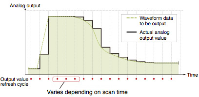 | The actual waveform and the output waveform deviate. |
Analog output with waveform output function Analog values are output at set interval. |  |
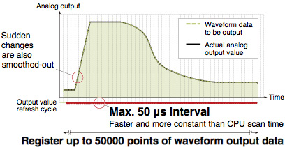 | The output waveform is closer to the actual waveform (less deviation). |
(1) Using GX Works2 to create the waveform output data to be analog output
(2) Save waveform output data into CPU module's file resister (or SD memory card)  *4: Contact your local Mitsubishi Electric sales office or representative. | (3) Execute the function block (FB)*4 and register  |
More flexible calculation and conversion reduce programming time
![]()
Conversion by polynomial expressions
The variable arithmetic function enables the analog I/O module to perform polynomial calculations, eliminating the need of such calculations programmed by ladder. With the calculations performed on the analog I/O module side, advanced calculations are possible without being restricted by the scan time
Graph-form conversion characteristics
The variable conversion characteristics function enables conversion characteristics for analog input, analog output, and analog I/O to be easily set on graphs. This means that conversion characteristics do not need to be programmed by ladder, which leads to reduced programming time.
| Item | Description |
|---|---|
| Analog input | Conversion characteristics can be easily set for the A-D conversion channels (CH1, CH2). |
| Analog output | Conversion characteristics can be easily set for the D-A conversion channels (CH3, CH4). |
| Analog I/O | Conversion characteristics for the analog input-output conversion can be easily set in simple steps, eliminating the need of creating ladder programs. |
The two functions described above can also be combined; the digital values are first converted according to graph-form conversion characteristics and then by polynomial expressions. These two levels of conversion realize full adjustment of analog values at the time of output rather than adjusting them post-conversion.
One module covering voltage, current, micro-voltage, thermocouples and RTD
![]()
For each channel, it is possible to select from voltage, current, micro-voltage, thermocouples or RTD. As a result, dedicated modules required for each type of sensor can now be integrated into a single module.
The multiple input module also supports the Pt50 and JPt100 sensors, which are compatible with the former JIS standards. Modules can be replaced without altering the already existing sensor equipment.
| Thermocouple | K, J, T, E, N, R, S, B, U, L, PL Ⅱ, W5Re/W26Re |
|---|---|
| RTD | Pt1000, Pt100, JPt100, Pt50 |
8 input channels with wider input ranges L60RD8
![]()
| RTD | Pt1000, Pt100, JPt100, Pt50, Ni (DIN standards), Cu (GOST standards) |
|---|
Reduced wiring time with no screw tightening
![]()
The module is equipped with a spring clamp terminal block, which does not require screw tightening. This push-in type terminal block does not require any dedicated wiring tool and significantly reduces the installation time.
Easier calibration
![]()
Measured temperatures can be easily calibrated towards the actual temperature using the sensor calibration function (shift function, 2-point sensor compensation function).