Product
Product Features
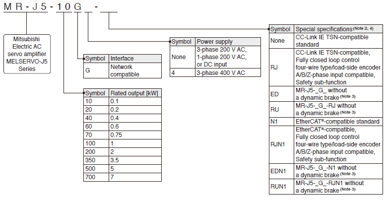
Model Designation for 1-Axis Servo Amplifier (Note 1)
G G-RJ
A A-RJ
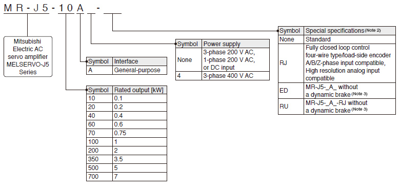
- Notes:
- This section describes what each symbol in a model name indicates. Some combinations of symbols are not available.
- For the servo amplifier firmware version compatible with each function, refer to "MR-J5 User's Manual".
- A dynamic brake which is built in the 7 kW or smaller servo amplifiers is removed. When the servo amplifiers without the dynamic brake are used, the servo motors coast to a stop and do not stop immediately at alarm occurrence or power failure. Take measures to ensure safety on the entire system. Refer to "MR-J5 User's Manual" for details.
- For the restrictions on the communication cycle, refer to "Restrictions" in MELSERVO-J5 catalog.
Model Designation for Multi-Axis Servo Amplifier (Note 1)
WG
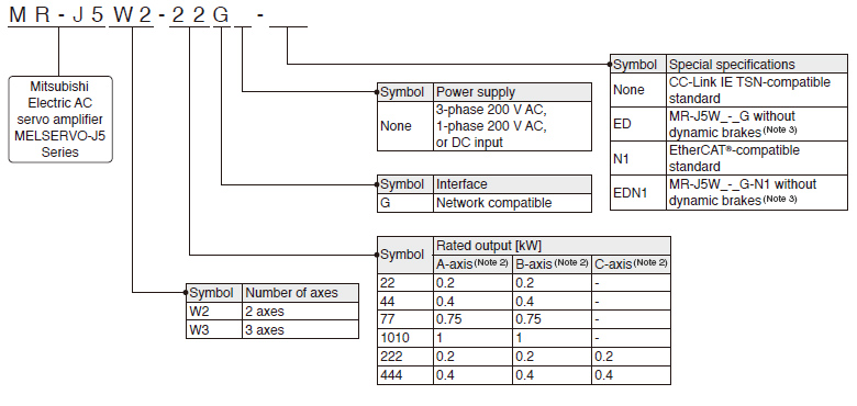
- Notes:
- This section describes what each symbol in a model name indicates. Some combinations of symbols are not available.
- A-axis, B-axis, and C-axis indicate names of axes of the multi-axis servo amplifier. The C-axis is available for the 3-axis servo amplifier.
- Dynamic brakes which are built in servo amplifiers are removed. When the servo amplifiers without the dynamic brakes are used, the servo motors coast to a stop and do not stop immediately at alarm occurrence or power failure. Take measures to ensure safety on the entire system. Refer to "MR-J5 User's Manual" for details.
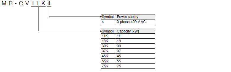
Model Designation for Drive Unit (Note 1)
DG
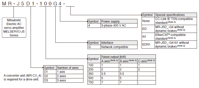
- Notes:
- This section describes what each symbol in a model name indicates. Some combinations of symbols are not available.
- Dynamic brakes which are built in drive units are removed. When the drive units without the dynamic brakes are used, the servo motors coast to a stop and do not stop immediately at alarm occurrence or power failure. Take measures to ensure safety on the entire system. Refer to "MR-J5 User's Manual" or "MR-J5D User's Manual" for details.
- MR-J5D1-G4(-N1) supports fully closed loop control four-wire type input and the load-side encoder A/B/Z-phase input as standard.
- A-axis, B-axis, and C-axis indicate names of axes of the multi-axis drive unit. The B-axis is available for the 2-axis drive unit and the 3-axis drive unit. The C-axis is available for the 3-axis drive unit.
Model Designation for Simple Converter
G G-RJ WG A A-RJ
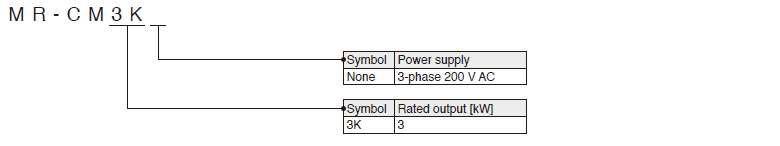
Model Designation for Power Regeneration Converter Unit
DG