


Product Features
Compact Servo Amplifiers with Simple Wiring
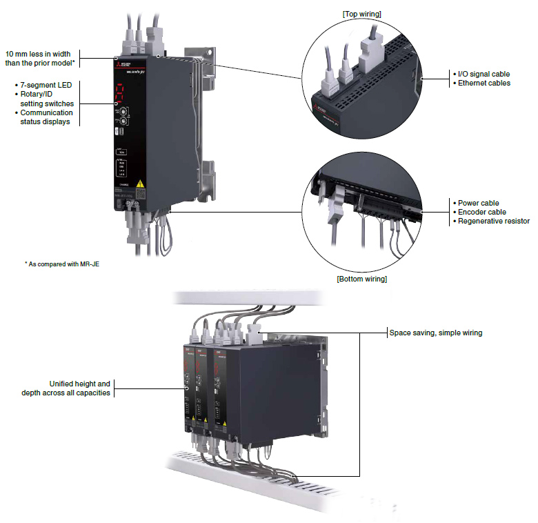
Simple, Efficient Wiring
The servo amplifier offers simple wiring by having connectors on the top and bottom surfaces, and allows all cables and wires to be routed through wiring ducts. LEDs and switches are located on the front surface of the servo amplifiers for easy operation.
Tuning Functions
Use the tuning methods that are optimal for your machines.
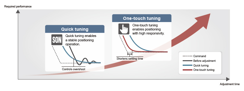
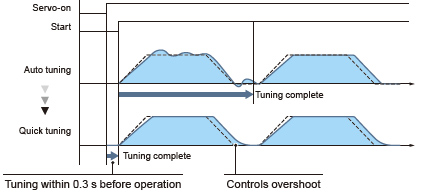
Quick Tuning
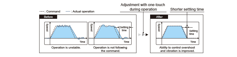
One-Touch Tuning
This function automatically completes servo gain adjustment according to the mechanical characteristics and reduces the settling time just by turning on the one-touch tuning. The servo gain adjustment includes the machine resonance suppression filter, advanced vibration suppression control II, and the robust filter. Controlling overshoot and vibration is improved, maximizing your machine performance.
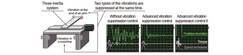
Advanced Vibration Suppression Control II
This function suppresses two types of low frequency vibrations, owing to vibration suppression algorithm which supports three-inertia system. This function is effective in suppressing residual vibration with relatively low frequency of approximately 100 Hz or less generated at the end of an arm and in a machine, enabling a shorter settling time. Adjustment is easily performed on MR Configurator2.
Command Notch Filter
The frequency can be set close to the machine vibration frequency because the command notch filter has an applicable frequency range between approximately 1 Hz and 2000 Hz.
Machine Resonance Suppression Filter
The expanded applicable frequency range is between 10 Hz and 8000 Hz. Five filters are simultaneously applicable, improving vibration suppression performance of a machine. The machine resonance frequency is detected by the machine analyzer function in MR Configurator2.
Preventive Maintenance
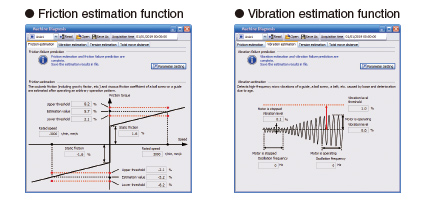
Machine Diagnosis Function
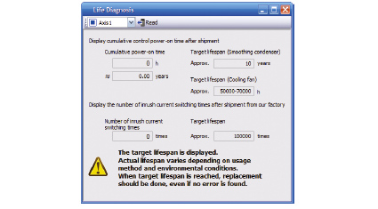
Servo Amplifier Life Diagnosis
Corrective Maintenance
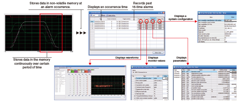
Drive Recorder
This function continuously monitors the servo status and records the status transition such as a trigger condition before and after an alarm for a fixed period of time. Reading the servo data on MR Configurator2 helps you analyze the cause of the alarm. In addition to the monitor values and the waveform of the past 16-time alarms in the alarm history, the system configuration and the servo parameters are displayed. Alarm occurrence time is also displayed when the servo amplifier and the controller are normally in communication on CC-Link IE TSN.
The data can be outputted to a GX LogViewer format file.
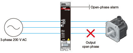
Connection/Communication Diagnosis
Disconnection Detection
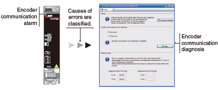
Encoder Communication Diagnosis
Supporting Flexible Driving System
Positioning by Using a CC-Link IE TSN-Compatible RJ71GN11-T2
Enhanced
functions
A CANopen-compatible master/local unit RJ71GN11-T2 can control the servo amplifiers. *1
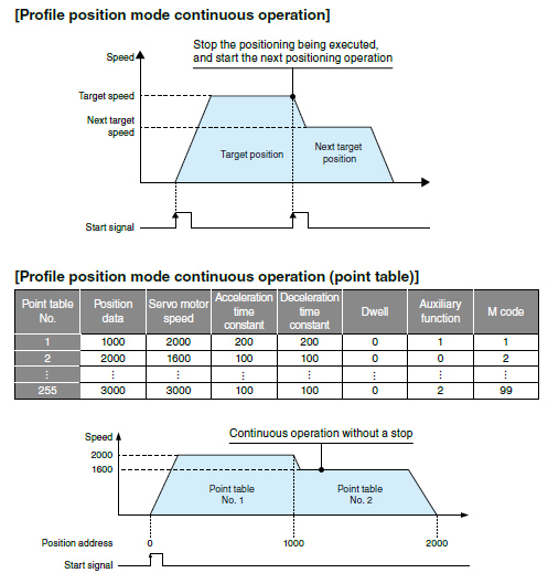
The servo amplifiers support the profile mode (position/velocity/torque) and the positioning mode (point table). *2
For example, in the profile mode, just by setting parameters such as a target position and a target speed and sending a start signal from the master station, the servo amplifier generates commands to the target position, starting positioning operation.
A positioning system is easily configured without a Positioning module.
- *1. RD78G/FX5-SSC-G Motion modules also support CANopen.
- *2. For the modes supported by the master station, refer to the master station specifications.
Path Control
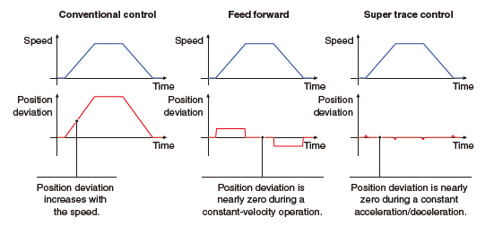
Super Trace Control
This function reduces a position deviation to nearly zero not only during constant-velocity operation, but also during constant acceleration/deceleration.
The path accuracy will be improved in high-rigidity machines.
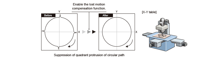
Lost Motion Compensation
This function suppresses quadrant protrusion caused by friction and torsion generated when the servo motor rotates in a reverse direction.
Therefore, the accuracy of circular path will be improved in path control used in XY table, etc.
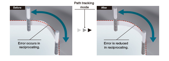
Path Tracking Model Adaptive Control
This function reduces path errors which occur when the servo motor reciprocates.
Normally, when positioning control is executed, the model adaptive control adjusts the control to shorten a settling time. Instead, this function reduces overshooting to improve path accuracy, which is suitable for machines that require high-accuracy path control such as processing machines.
Command Interface
CC-Link IE TSN JET-G
Enhanced
functions
The servo amplifiers drive the servo motors by receiving commands (position/velocity/torque) at regular intervals in synchronous communication with the CC-Link IE TSN-compatible controller.
When combined with a Motion module or Motion Control Software, the servo amplifiers enable exact synchronous operation of axes and machines through high-speed, high-precision time synchronization.
The servo amplifiers support CiA 402 drive profile and enable the profile mode (position/velocity/torque) and the positioning mode (point table). When combined with the controllers supporting the profile mode, the servo amplifiers generate a positioning command to a target position, reducing loads of the controllers.

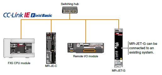
CC-Link IE Field Network Basic JET-G
Enhanced
functions
CC-Link IE Field Network Basic-compatible master stations such as an FX5U CPU module can control MR-JET-G servo amplifiers. The servo amplifier can be operated as a CANopen device via a link device.
The profile mode (position/velocity/torque) and the positioning mode (point table) are supported.
MR-JET-G servo amplifiers can be connected to existing systems using MR-JE-C.
In addition, MR-JET-G newly supports the line topology. *1
- *1. When a device which does not support the line topology is used, the line/star mixed topology is applicable.