


Product Features
Industry-Leading Basic Performance
Industry-Leading Level of Servo Amplifier Basic Performance
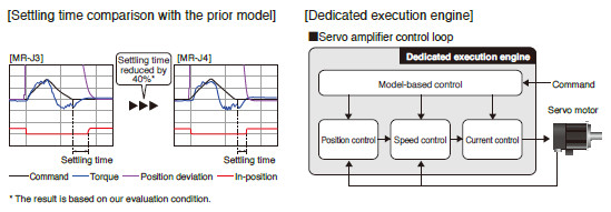
A speed frequency response of 2.5 kHz is achieved by applying our original high-speed servo control architecture evolved from the conventional two-degrees-of-freedom model adaptive control to the dedicated execution engine. Together with a high-resolution absolute position encoder of 4,194,304 pulses/rev, fast and accurate operation is enabled. The performance of the high-end machines is utilized to the fullest.
Improving Machine Performance with High-Performance Servo Motors
With improved processing speed, the rotary servo motors equipped with a high-resolution encoder enables high-accuracy positioning and smooth rotation.
Advanced Servo Gain Adjustment Function
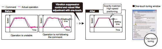
One-Touch Tuning
Just turn on the one-touch tuning function to complete servo gain adjustment automatically, including machine resonance suppression filter, advanced vibration suppression control II*1, and robust filter for maximizing your machine performance. This function also sets responsivity automatically, while the real-time auto tuning requires manual setting. Moreover, a new method*2 allows to create an optimum tuning command inside the servo amplifier.
- *1.The advanced vibration suppression control II automatically adjusts one frequency.
- *2.This new method is supported by MR-J4-B/MR-J4W_-B/MR-J4-A.
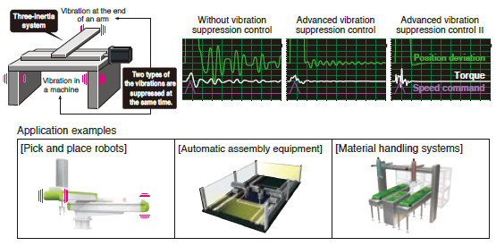
Advanced Vibration Suppression Control II
The advanced vibration suppression control II suppresses two types of lowfrequency vibrations, owing to vibration suppression algorithm which supports three-inertia system. This function is effective in suppressing residual vibration with relatively low frequency of approximately 100 Hz or less generated at the end of an arm and in a machine, enabling a shorter settling time.
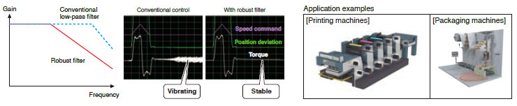
Robust Filter
Achieving both high responsivity and stability was difficult with the conventional control in high-inertia systems with belts and gears such as printing and packaging machines. Now, this function enables the high responsivity and the stability at the same time without adjustment. The robust filter gradually reduces the fluctuation of torque in a wide frequency range and achieves more stability as compared to the prior model.
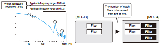
Expanded Machine Resonance Suppression Filter
With advanced filter structure, applicable frequency range is expanded from between 100 Hz and 4500 Hz to between 10 Hz and 4500 Hz. Additionally, the number of simultaneously applicable filters is increased from two to five, improving vibration suppression performance of a machine.
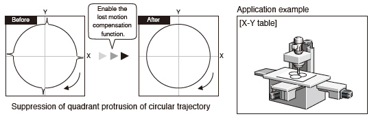
Lost Motion Compensation Function
This function suppresses quadrant protrusion caused by friction and torsion generated when the servo motor rotates in a reverse direction. Therefore, the accuracy of circular path will be improved in trajectory control used in XY table, etc.
- * This function is not supported by MR-J4W2-B and MR-J4W3-B.
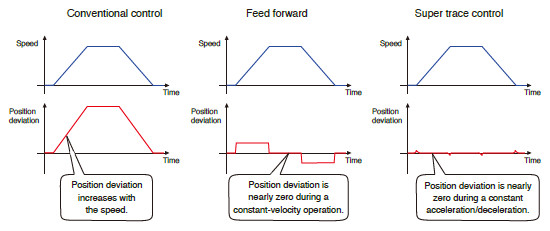
Super Trace Control
This function reduces a position deviation to nearly zero not only during constant-velocity operation, but also during constant acceleration/deceleration. The trajectory accuracy will be improved in high-rigidity machines.
- * This function is not supported by MR-J4W2-B and MR-J4W3-B.
A Variety of Functions for Various Applications
* Use a compatible controller.
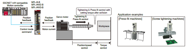
Tightening & Press-Fit Control

This function switches position/speed control mode to torque control mode smoothly without a stop or a sudden change in speed and torque, and thus reduces load to a machine. This function is best suit for an application where control is switched from position to torque such as Tightening & Press-fit control or insertion of a work, and cap or screw tightening.
- * This function is supported by MR-J4-B/MR-J4W2-B/MR-J4W3-B.
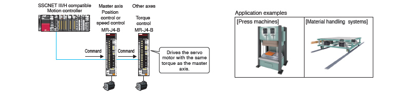
Master-Slave Operation Function
The master-slave operation function enables the torque of the master axis to be transmitted to the slave axes via SSCNET III/H and to control the slave axes with the same torque as the master axis. No special wiring is necessary.

Compatible Servo Motors

- * Refer to the following for the possible combinations of servo motors and servo amplifiers.
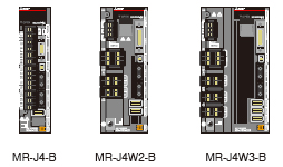
1-axis/2-axis/3-axis Servo Amplifiers
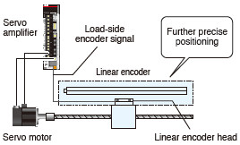
Supporting Fully Closed Loop Control
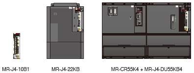
Wide Range of Power Supplies and Capacities
MR-J4-GF(-RJ) and MR-J4-A-RJ with Built-in Positioning Function
MR-J4-GF(-RJ) and MR-J4-A-RJ have a built-in positioning function, enabling positioning operation with point table, program-based*, and indexer methods. With these servo amplifiers, a positioning system is configured without a Positioning module (command pulse). Positioning command is executed by CC-Link IE Field network, input/output signals, or RS-422/RS-485 communication (up to 32 axes). MR Configurator2 allows easy setting of the positioning data.
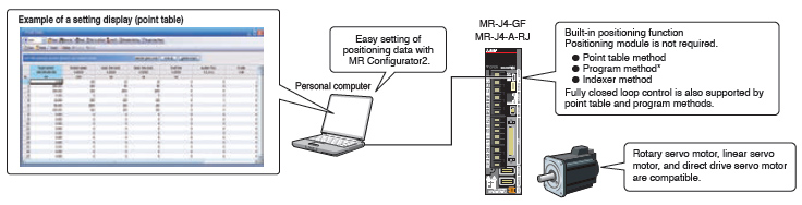
- * The program-based method is supported only by MR-J4-A-RJ.
Point table method

Set position data (target position), servo motor speed, and acceleration/deceleration time constants in point table. Setting the point table data (settable up to 255 points) is as easy as setting parameters. Perform positioning operation with a start signal after selecting the point table Nos.
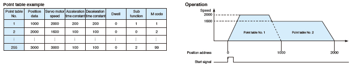
- * For MR-J4-A-RJ, point table can be set with push buttons on the servo amplifier or with MR-PRU03 parameter unit.
Program method*

Create positioning programs with dedicated commands, and perform positioning operation with a start signal after selecting the program Nos. The program-based method enables more complex positioning operation than the point table method. Maximum of 256 programs are settable. (The total number of steps of all programs: 640)
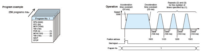
- * MR Configurator2 is required to create programs.
Indexer method*
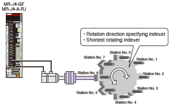
* Not supported by MR-J4-03A6-RJ.
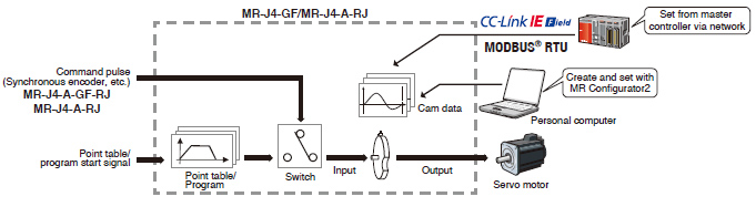
New useful functions are added to the positioning function: simple cam function, encoder following function, pulse input through function, simple cam position compensation function, and communication functions (MODBUS® RTU, Point to Point positioning, and current position latch function). Apply these useful functions to a wide variety of applications to configure positioning system easily.
Simple cam function
Various patterns of cam data are created easily with MR Configurator2. Command pulse or point table/program start signal is used as input to the simple cam. The input command will be outputted to the servo motor according to the cam data.
- * The program-based method is supported only by MR-J4-A-RJ.
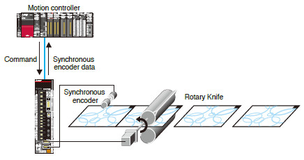
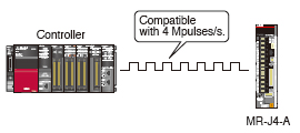
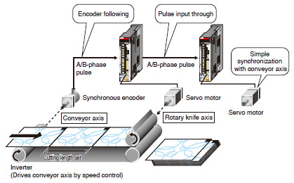
Encoder following function/Pulse input through function*

With the encoder following function, the servo amplifier receives A/B-phase output signal from the synchronous encoder as command pulse, and the input command will be outputted to the servo motor according to the cam data. Setting cam data that matches with the sheet length, a circumference of the rotary knife axis, and the synchronous section of the sheet enables a system in which the conveyor axis and the rotary knife axis are synchronized. Up to 4 Mpulses/s of input from a synchronous encoder is compatible with the servo amplifier. The pulse input through function allows the first axis to output A/B-phase pulses which are received from the synchronous encoder to the next axis, enabling a system in which the subsequent axes are synchronized with the synchronous encoder.
- * The pulse input through function is available as A/B-phase pulse input through function for MR-J4-GF-RJ and as command pulse input through function for MR-J4-A-RJ.
Simple cam position compensation function*